View Basket

This thread has been locked and can no longer be posted to.

Where to start?

Posted at 15:04:57 Wed 6 Oct 2021

Hello everyone, glad to finally be here.

I have wanted a Hornby train set since I was a child, and now I have the means to finally invest some time and money, I’m lost at where to start. I have recently begun to board my loft space, as it’s something I’ve long wanted to do, and realised I would have enough space to assemble some track, and later on, some landscape.

I have begun to watch beginner videos and how to get started, but I have to admit that I feel a bit overwhelmed with where to start.

My plan was to start with a starter set, more specifically the R1271M iTraveller 6000 set, because it comes with the HM 6000 which I really like the look of.

I have come here to ask the experts what are a few of the do's and don’ts when starting out? It feels like this is a hobby where the sky is the limit in terms of how much you can spend, both in time and money, and how much space you can use.

I really like the look of the DDC, but is this for more advanced users, or is it something you can use from the start?

The RailMaster seems like something for large scale setups with multiple trains and connections, so is this something I should avoid until I’m more comfortable with how everything works?

I did try to keep this short, but there is so much I’d like to ask. For now, I’ll leave it here. If you have read all the way to this point, thank you, you’re a real trooper.

Thanks all.

My name is long, so just call me Lee.

Last Edited 15:08:30 Wed 6 Oct 2021
Posted at 19:48:06 Fri 8 Oct 2021

The siding to the left of A8 could be reversed placing the point back to back with A8 feeder to give you more siding length into the corner and may help with the A7 slope.

Top road in A5 makes a Wye junction which is reverse loop. See Chris’ guide about such things. At present the stub track allocated to a future extension isn’t long enough to be of any use so for now make it a continuous loop as per your own suggestion until then.

Gradients need to be held to 2% or 1 in 50 else modern locos will struggle. This can be onerous to achieve on a short run like A7. Curves effectively steepen a slope due to friction dragging on rolling stock. Mine is about 12 foot run to rise just under 3 inches. As important as the slope angle is the transition from flat to hill and back to flat again. More of how to achieve that later. There cannot be any angle or too tight a bend up and over or your stock will lose contact with the track and likely derail. As stated you can plan this flat and wing the slope later by trial and error but keep it in mind.

Make anywhere that will be a station long enough to park a typical length train there. Advice I was given by members and gladly adopted on my layout.

http://www.halton96th.org.uk/robs_rails.html

Last Edited 19:55:43 Fri 8 Oct 2021
Posted 19:48:06 Fri 8 Oct 2021

Posted at 19:56:52 Fri 8 Oct 2021


If my mental arithmetic has interpreted the plan correctly, the inner oval and the reverse curve leading to area 5 use radius 1 curves. If that is so, you will be restricted in the types of loco you can run over those tracks as most of the larger ones are able to negotiate only radius 2 upwards.


Posted 19:56:52 Fri 8 Oct 2021

Posted at 20:12:16 Fri 8 Oct 2021

96RAF - The idea about switching the siding at A8 is brilliant. Turning it around and making use of that corner is excellent, even more so as they can be reversed in.

I didn’t really make it clear. The slope would effectively start at the start of A7, and continue upwards all the way to the end of A8. However, with what you’ve said, maybe this idea was a bit too ambitious and I’ll not have enough room to make the gradient safe. I’ll have a rethink about what to do here.

There will only be one station, next to the church, using a small loco and three passenger carriages, with a curved station. However I feel it may not be quite long enough to follow your advice. More rethinking.

Going Spare - I plan to only use small locos on the inner oval, but as you point out, A5 may cause some problems. I’m not entirely happy with that whole area, but I couldn’t find another way to make it work. I think I’ll have it curve back round to the left to create another oval. Do you think this idea would be better?

My name is long, so just call me Lee.

Last Edited 20:31:24 Fri 8 Oct 2021
Posted 20:12:16 Fri 8 Oct 2021

Posted at 20:27:22 Fri 8 Oct 2021

Just to clarify one of Rob's comments. The WYE reverse loop he identified creates a short circuit. This is easier to deal with on a DCC powered layout than on a DC powered layout. If DC, then the wiring will need a DPDT (Double Pole Double Throw) switch incorporated. Additionally, regardless of whether DC or DCC powered, the WYE section will need IRJs (Insulated Rail Joiners) inserted at strategic locations to prevent the WYE reverse loop induced short circuit from tripping the controller.

This layout design is also deploying a large number of curved points, some of them sequentially one after another. Hornby curved points have a notorios reputation for causing rolling stock derailments. Most members on this forum who have experienced these Hornby curved point derailment issues recommend avoiding their use OR substituting the Hornby curved points with PECO branded ST curved points that appear less prone to derailment issues.

There are also a large number of locations where points have been placed 'back to back'. That is to say, they have their 'toe' ends facing each other. The point 'toe' is the common end. In a DC powered layout this can create dead sections of track when certain routes are set through the points on the layout. Hornby points are termed 'isolating points' and act as electrical switches to only route power into the route that they are switched to. This requires the power from the controller to be applied to the 'toe' end of the point. Where the 'toes' are facing each other, then point routes can be set that isolate the 'toes' from the controller power connection location. Again, this issue can be resolved through 'custom' power wiring the layout, but is not really a skill expected of a novice layout builder.

Unfortunately, what looks good on paper, particularly when squeezing in a lot of layout into a small space, ends up not being very practicable to implement from a controller powering point of view. Not helped by the issues that seem to be factory implemented in Hornby track products such as the well documented curved points derailment issue.

Even the standard Hornby points can be prone to derailment and seem to be more reliable from a derailment point of view when directly connected to a straight, rather than a curve or another point. The downside being that additional straights included to reduce the risk of derailments impact the overall size occupied by the layout.

Chris.......Making the 'Wood in the Trees' visible.

Last Edited 22:50:37 Fri 8 Oct 2021
Posted 20:27:22 Fri 8 Oct 2021

Posted at 20:59:15 Fri 8 Oct 2021

Dang, and I thought I was doing well there for a moment.

Do you have any suggestions to rectify the issues you pointed out, Chris?

My name is long, so just call me Lee.

Last Edited 21:55:54 Fri 8 Oct 2021
Posted 20:59:15 Fri 8 Oct 2021

Posted at 21:53:01 Fri 8 Oct 2021

When it comes to designing 'custom' power plans for DC layouts, that is something I have done for a number of members in these forum pages. It does help however if you have the capability to perform some basic soldering, such as soldering wires to rails (Nickle Silver rails not Steel ones).

Your current design only has one single continuous loop, and relies more on 'end to end' train movements for play value. Personally, I would look to design a layout with two loops plus sidings and try to keep it more simple for a first layout. I would definitely lose the WYE triangle section as this can be onerous to support in a DC Analogue powered layout. Try to reduce the overall number of points so that you can introduce some straight track between consecutive points. The straights also give a track piece where track power connectors can be placed, negating the need for excess soldering. If you must have curved points, then look to use the PECO ST ones.

Personally, I would abandon the thought of including gradients to a second level. I appreciate that levels introduce significant scenic interest (I have three levels in my own layout) but they are just not practical in a typical members 8 x 4 sized layout when using modern lighter less powerful locomotives as you need a good 8 foot run of straight track to rise a sufficent height to clear trains running underneath. Including a curve in a gradient track section increases drag significantly. My own gradients struggle to pull anything longer than two or three coaches. In hindsight, knowing what I know now, I would not have implemented gradients in my layout design as they take up so much space in my layout footprint. Instead I would have built a layout with two levels that were each completely flat and physically isolated from one another. Thus the scenic interest is there, without any of the gradient issues.

The carpentry for a dual layer baseboard requires a little more skill, but you could have two lower level loops with a few sidings and an upper level loop (or upper level 'end to end') for scenic interest. The upper level track could cross over the lower tracks in a couple of places via bridges, again for scenic interest.

If you did implement a physically isolated upper level 'end to end' section, then that opens up the possibility of installing a DC Analogue shuttle controller. That would allow a train to autonomously transit back and forth across the upper section 'station to station' under its own control providing some moving scenic interest, whilst you focus on manually driving the trains on the lower level with your layout controllers. The DC Shuttle controllers include adjustable timers to define how long the train stays in the end stations before starting its return journey.

In other words, what I am trying to convey is that good scenic design can give a far more realistic and interesting looking layout, than trying to cram in as much track as possible. By reducing the amount of track, then it might also be possible to eliminate the Radius 1 curves that were highlighted as an issue by G.S.

Chris.......Making the 'Wood in the Trees' visible.

Last Edited 23:02:03 Fri 8 Oct 2021
Posted 21:53:01 Fri 8 Oct 2021

Posted at 22:44:58 Sat 9 Oct 2021

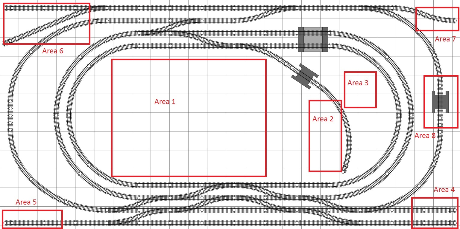
I'm having lots of fun with the AnyRail software. Still a complete noob, but I'm learning more each time I use it. Using the track geometry PDF that 96RAF posted has been a massive help and I've been using it a lot.

After the feedback here, and spending more time using AnyRail, I've come to the conclusion that my first attempt had many problems, but it was all valuable experience.

I moved onto my second layout, I feel like I'll make several more before I get to one that I'm happy with. However, I like a lot of the features from my second attempt.

The areas are:

1 - Town or village.

2 - Curved station. (I'm not happy with this area and would prefer a straight station, so I'll likely rework this area)

3 - Church or similar building.

4 - Twin tracks that will lead to another area for future expansion. Used for shunting until then.

5 - Unlikely to ever expand this way due to loft layout, so I may remove this area, or use it as a siding.

6 - A siding and a single loco shed.

7 - This is another future expansion area that will lead into a tunnel. I made it slightly curved to accommodate the landscape needed for a tunnel structure.

8 - I had to cut the top right corner off of my outer oval to make enough room for a road in and out of the town. The town will be accessed via a tunnel in this area.

I've decided to scrap my plans for any elevation changes. I like the idea of another level with another separate track, which was suggested by Chrissaf, but for my first layout, I'll keep it all level. I'll keep tinkering with more layouts. I'll try a few smaller ones and see if I like how it looks.

My name is long, so just call me Lee.

Last Edited 08:51:20 Sun 10 Oct 2021
Posted 22:44:58 Sat 9 Oct 2021

Posted at 07:54:56 Sun 10 Oct 2021

Looking better, with more running capability.

Unless you need the white space twixts A5&6 formscenics I would be tempted to move those inner curves left which will allow your main town to move left and may improve your A2 station, possibly giving room for a pair of tracks either side of a platform or two platforms. The main town does not have to be square hence you could angle your station road in across a corner.

The main town could be arranged as a lift out board to give temp access when required as previously suggested.

http://www.halton96th.org.uk/robs_rails.html


Posted 07:54:56 Sun 10 Oct 2021

Posted at 08:42:36 Sun 10 Oct 2021

DRC,

I am concerned about the cluster of points in the centre bottom and invite other members to comment. I understand why you have proposed that arrangement but I would be worried about trains derailing if 'snaking' through four sets alternating left/right i.e. if your train is transitioning from the inner to outer circuit, or visa versa. You could probably remove 4 points and still get across the loops but by simply running around the middle loop as an intermediate stage. Just something to think about, and it would save a little bit of money!

Last Edited 08:53:51 Sun 10 Oct 2021
Posted 08:42:36 Sun 10 Oct 2021

Posted at 09:41:30 Sun 10 Oct 2021

Hi DRC

Your 2nd plan looks good but have you taken into account the length of Locomotives, coaches and trucks, Small locos and trucks are about the size of a R600, larger locomotives, bogie coaches and bogie trucks are roughly a R601 double straight.

A 4 6 0 plus 3 coaches is over 3 foot in length A class 91 with 3 MK4 and a DVT is over 4 foot.

It is something you need to take into consideration when planning a layout


Posted 09:41:30 Sun 10 Oct 2021

Bassett-Lowke Members Login

Forgotten Your Password?

Need to Register?